Cart
Your shopping cart is empty!
It's never too late to make things right :)
Installing the antenna requires you to first modify the controller. The process requires removing the standard external antennas, as well as internal antenna modules, and then installing in their place antenna adapters that output the signal outside the transmitter housing.
Attention! The modification process includes both opening the controller case and drilling two holes on its top panel (necessary for the output of SMA connectors).
Before modifying, review this step-by-step guide to make sure you have the necessary tools to modify your controller.
You should have a set of quality tools for disassembling electronic devices (such as mobile phones/tablets, etc.). They are extremely useful and will greatly speed up the disassembly process. Prepare a set of fine-tip screwdrivers, both Phillips and hex. If this is your first time disassembling the controller, be prepared for a bit of a challenge - both halves of the case are almost perfectly sealed, and it may take some time to open it. Take your time and do not use excessive force or sharp tools as you may damage the casing. Use a soft pad (best soft, thick material) when placing the controller on a table to protect the LCD screen. It is also a good idea to group and label the removed screws in separate bags to avoid losing them or misusing them.
Ready ? Then go ahead!
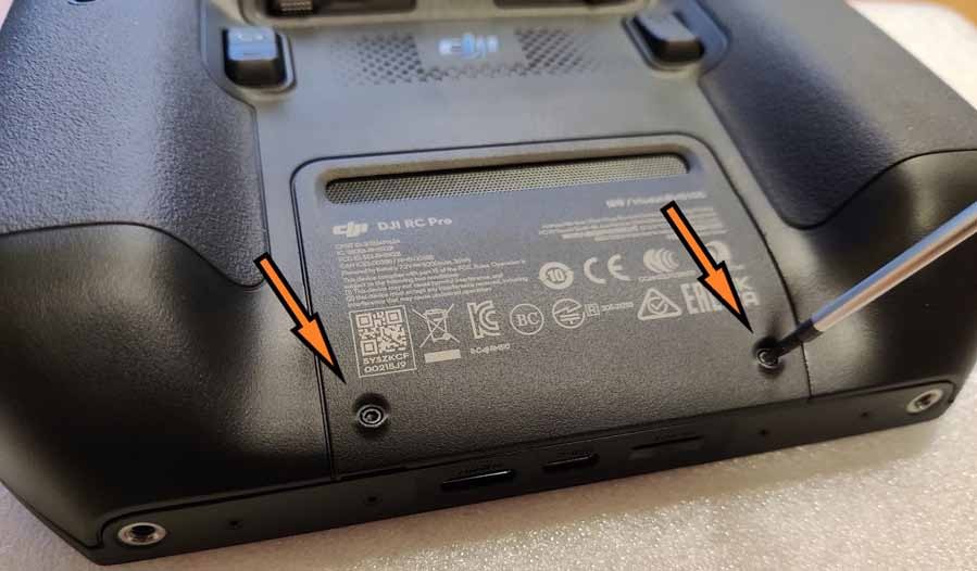
Step 1:
Remove the 2 screws from the battery cover to open the battery compartment.
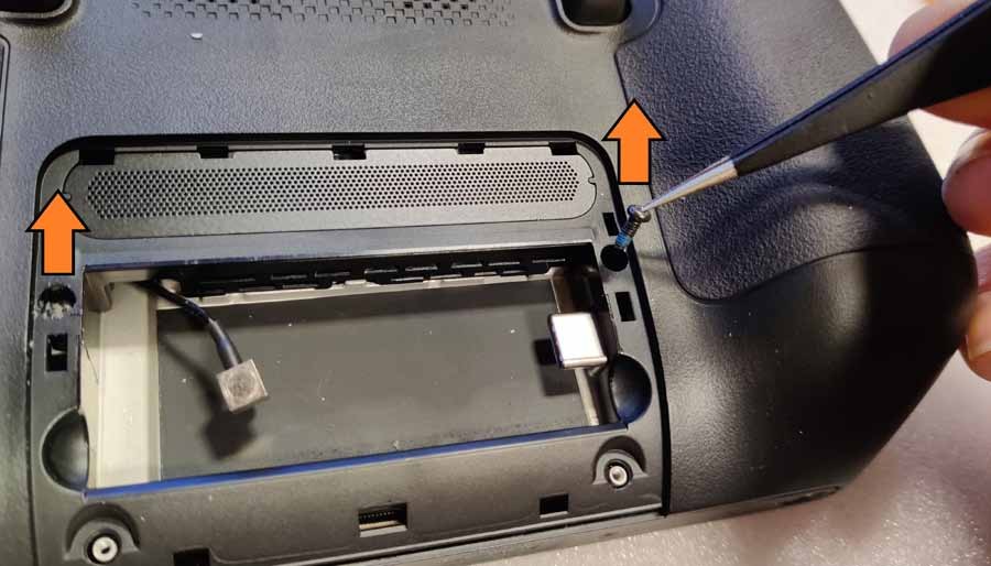
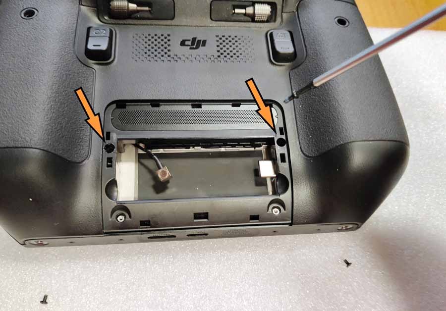
Step 2:
Remove the 2 screws on both sides of the battery compartment. Carefully! The left one is usually sealed with silicone! They probably won't pop off on their own, so use sharp tweezers to remove them.

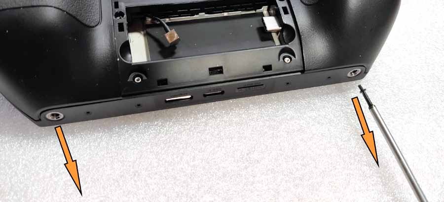
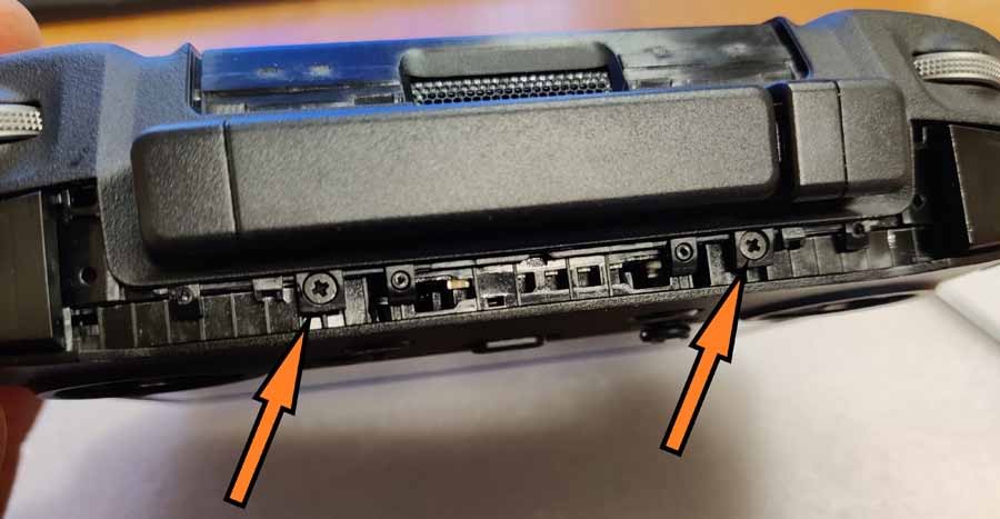
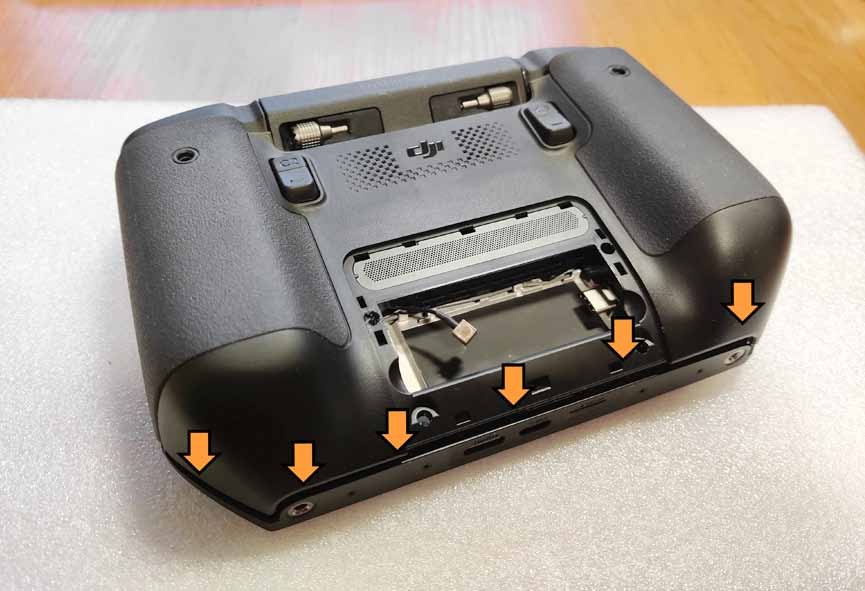
Step 3:
Remove the 2 screws from the bottom holes.
Step 4:
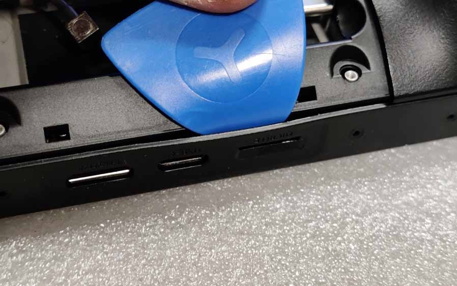
Open the case. Using soft plastic tools, lift up the body parts and remove the hooks holding the body in place from the inside. Start from the middle part where the HDMI and USB ports are located, and move left and right sequentially and simultaneously.
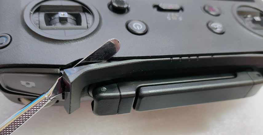
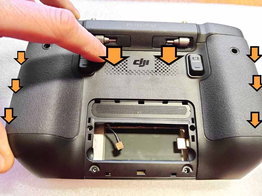
Step 5:
Now use a soft plastic tool to press between the handle and the housing on the side seal to lift it up. While holding the tool, use another to lift each subsequent hook. Move down to the HDMI and USB ports on the bottom of the case. Move forward sequentially, hook by hook, being careful not to scratch the body and screen.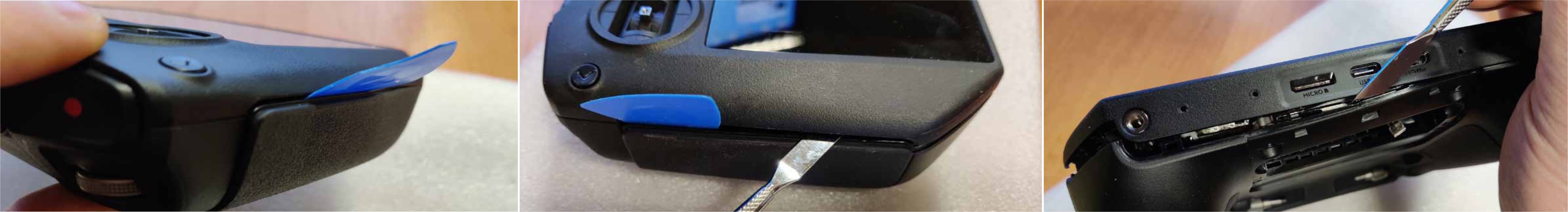
Step 6:
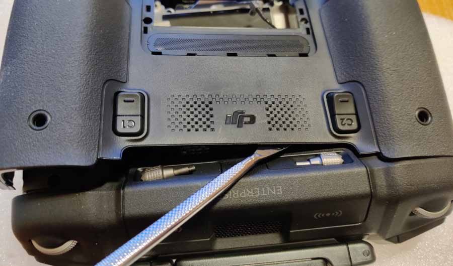
Open the back cover to the line just above the "DJI" logo on the back. Move from side to side, releasing one hook after another in sequence.
Step 7:
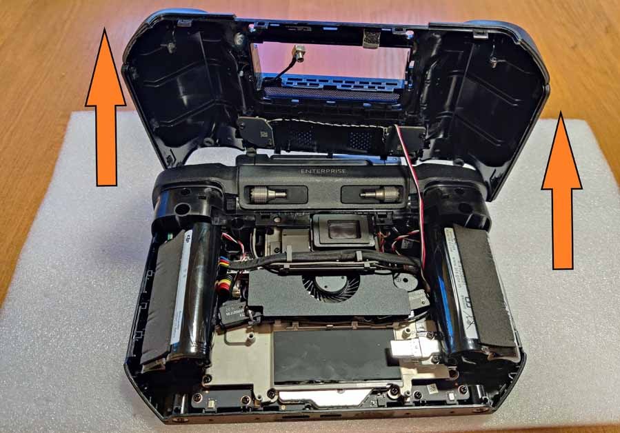
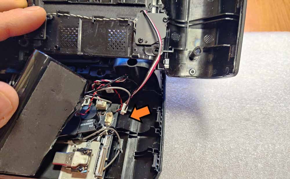
Open the back cover carefully! three-wire wire connected!
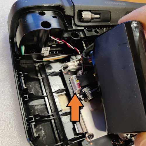
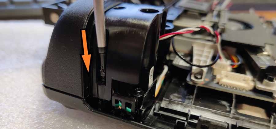
Step 8:
Disconnect the wire. The port is located directly below the right battery cell. Place the detached rear section in a safe place.
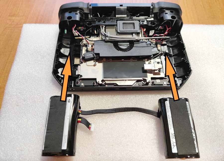
Step 9:
Remove both battery cells. Pay attention to the hooks that hold the wire connecting both cells - carefully remove it. The port connecting the batteries to the circuit board is located under the left cell. Place disconnected batteries in a safe place.
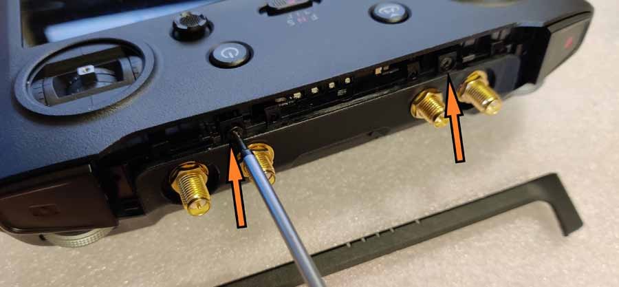
Step 10:
Now remove the top panel of the controller. First, unscrew the 2 screws from the left and right edges.
Step 11:
Remove the two screws securing the top of the controller.
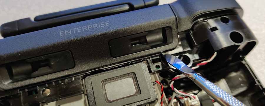
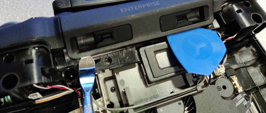
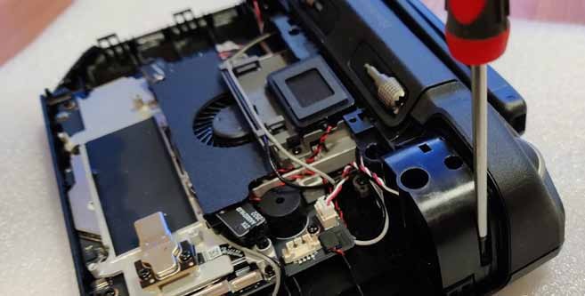
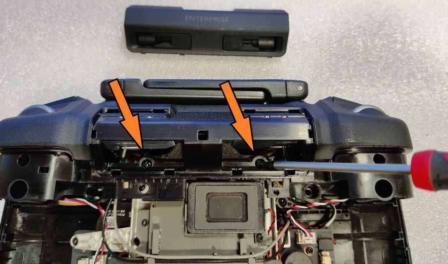
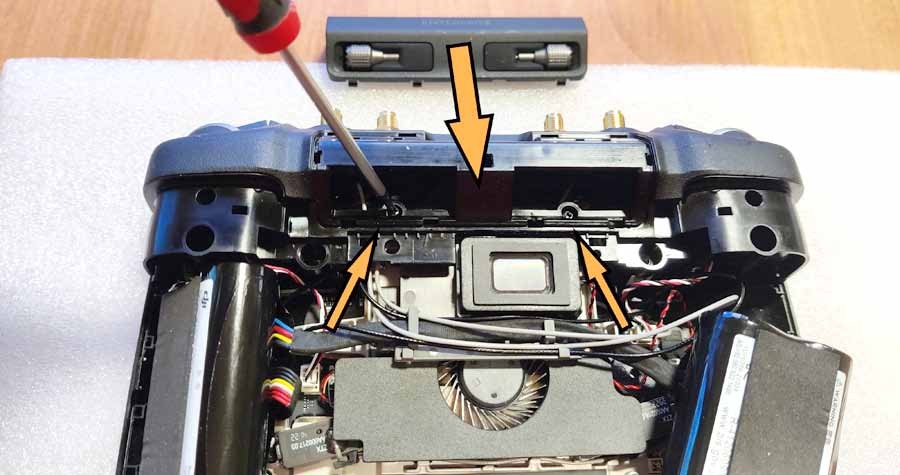
Step 12:
After removing the part with the rubber stick holders, unscrew the 2 screws shown below.
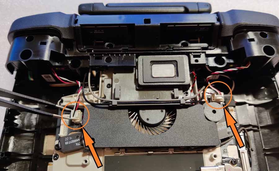
Step 13:
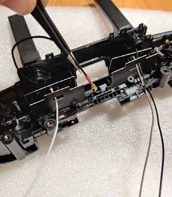
Disconnect the 2 wires on the left and right. Be careful not to damage thin wires when pulling them out of the ports.
Step 14:
Remove the top panel (holding the antennas). Start with the LED display panel by lifting it up on both sides. It fits quite tightly, so you have to pull it out from both sides at the same time. Be careful not to break or bend it at its thinnest point.

Step 15:
Now remove the 2 screws located under the LED panel.
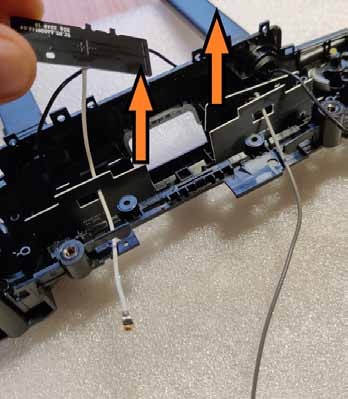
Step 16:
Continue removing the top panel. Start on the left or right side, carefully lifting the panel up. As always, use a soft plastic tool as a wedge when lifting the other hook. When you lift the left side, lift the right.
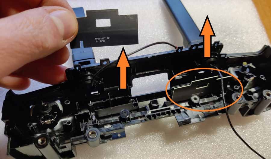
Step 17:
When there are no longer any hooks or screws holding the top panel in place, carefully detach it from the main body.

Step 18:
Pay special attention to the white (x1), gray (x1) and black (x2) antenna cable when lifting the top panel! They are firmly attached and you may accidentally pull them out by applying too much force. To begin, remove the gray and black cable from the hooks.
Step 19:
Remove the 2 screws from the antenna module in the detached top panel.
Step 20:
Remove the middle plastic piece holding the antenna boards.
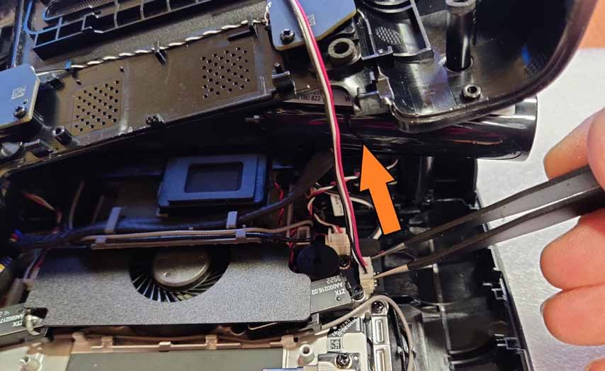
Step 21:
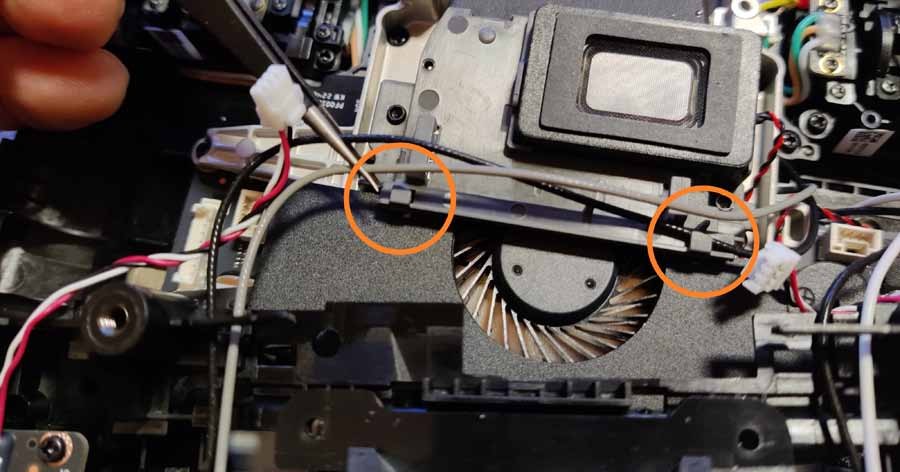
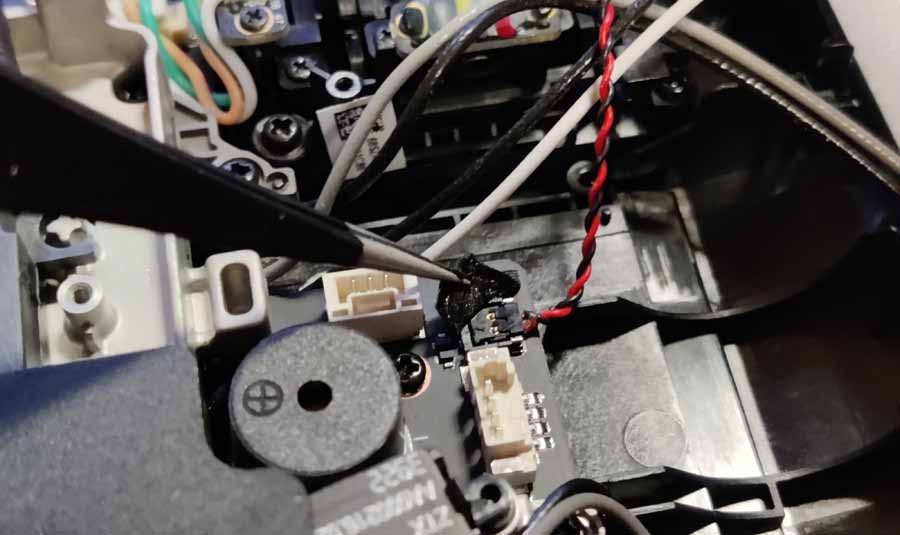
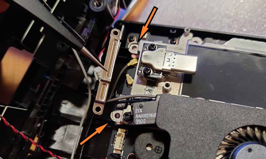
Remove the antenna cables from the antenna module located on the PCB. First remove the gray fan cover by removing the 2 small hex head screws. Be careful with the red-black cable! You can disconnect it completely by removing the plug from the port hidden under the protective cloth (but you can also leave it there if it doesn't interfere with your work).
Step 22:
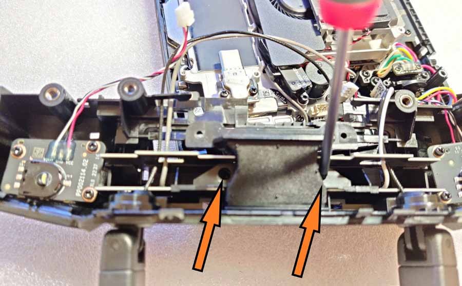
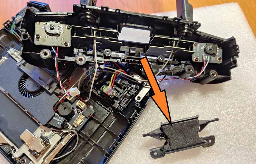
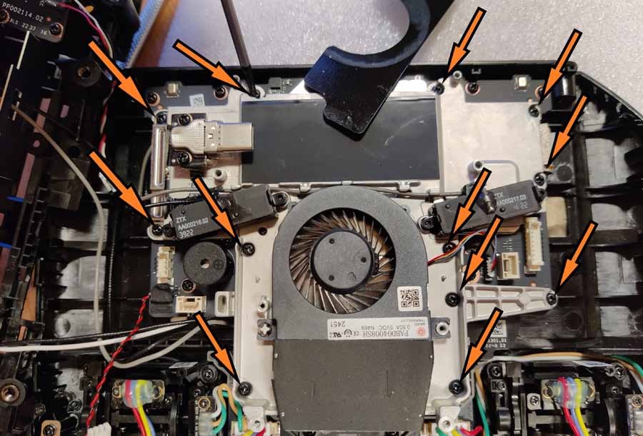
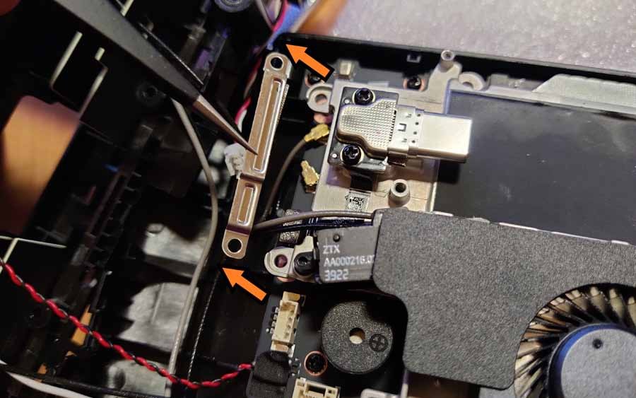
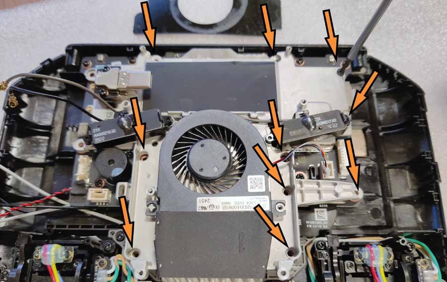
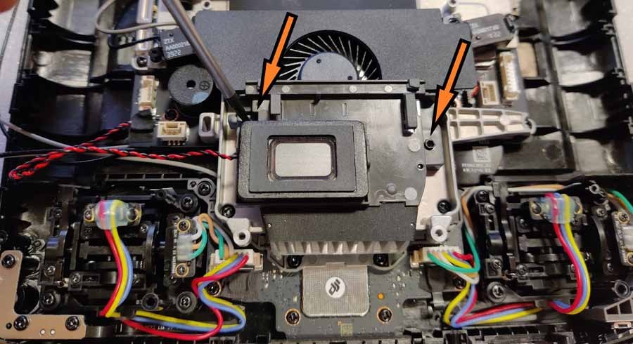
Remove the fan along with its housing - it is held in place by 12 screws (two of them remain hidden under the plastic cover!). Please note that 2 screws also secure the metal security bracket covering the 2 U.FL ports. Carefully remove it and store it in a safe place.
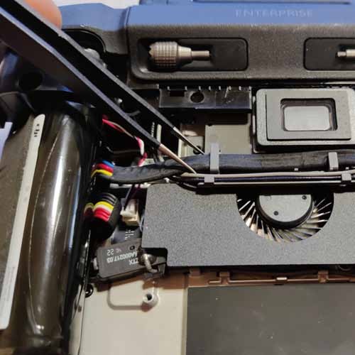
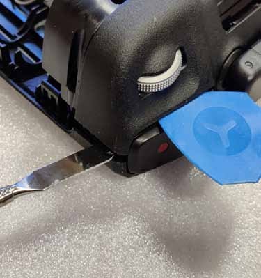
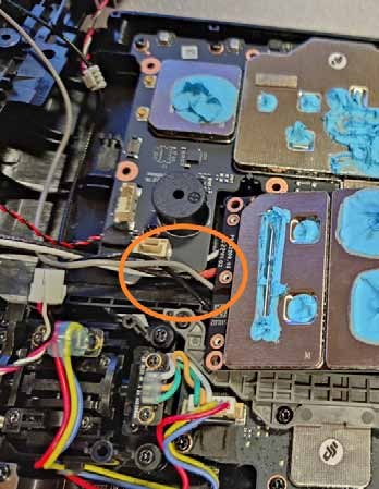
Step 23:
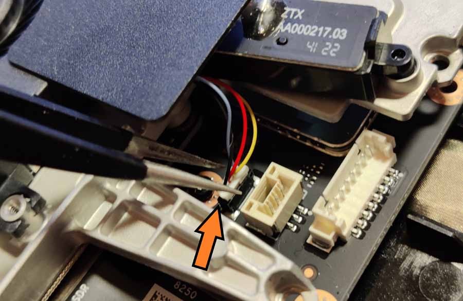
With all 12 screws removed, carefully pull the 3-wire cable out of the port on the right side.
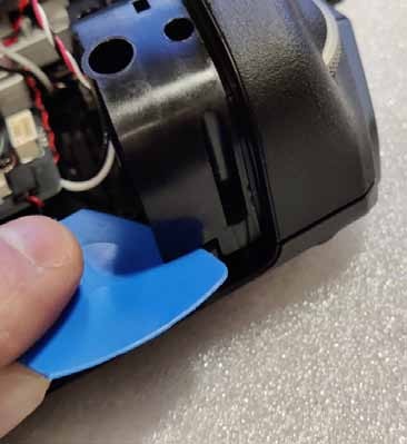
Step 24:
Now lift up the part with the fan (be careful! There is thermal paste at the bottom).
Step 25:
Remove the 2 U.FL plugs from their sockets and keep the fan part in a safe place.
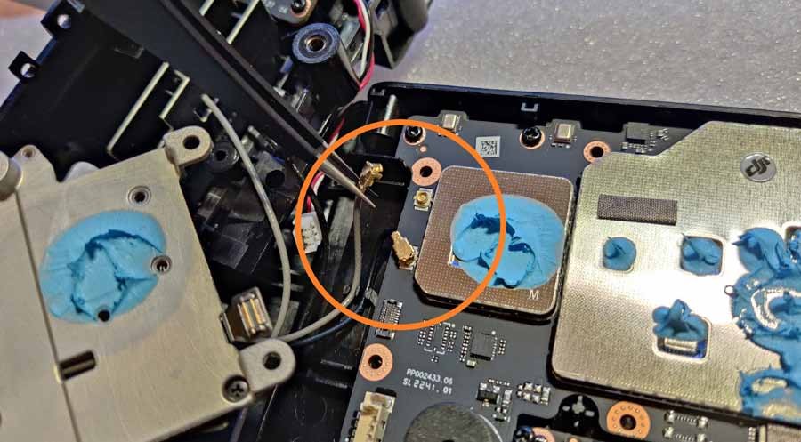
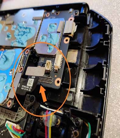
Step 26:
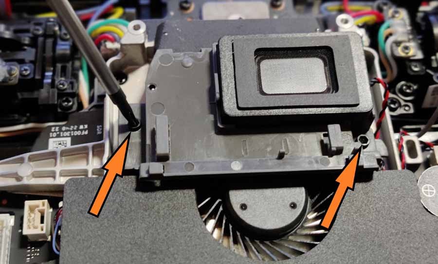
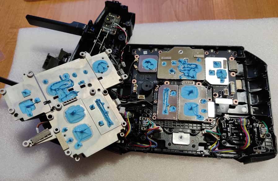
Remove the transmission module from the circuit board. Notice the port under the metal protective sheet on your right. Carefully lift it up, carefully guiding the cables to the left of the circuit board.
Step 27:
The antenna cables are located under the transmitting module and secured with a metal bracket. Take a photo to remember the order of connecting the cables to the 4 ports.
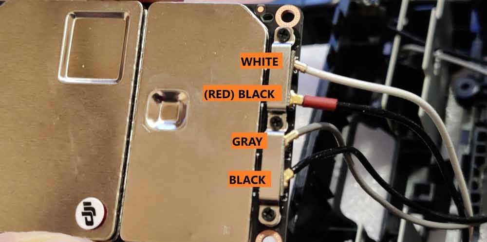
Step 28:
Removing 2 of the 3 screws should now allow you to remove all 4 U.FL connectors from their sockets. Take a photo or write down the order of the cables connected to the ANT0, ANT1, ANT2 and ANT3 ports as this will be important later.
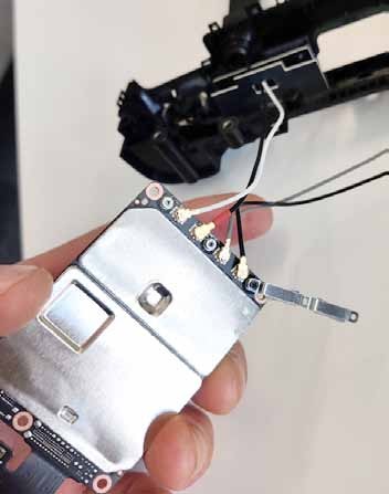
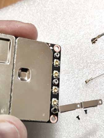
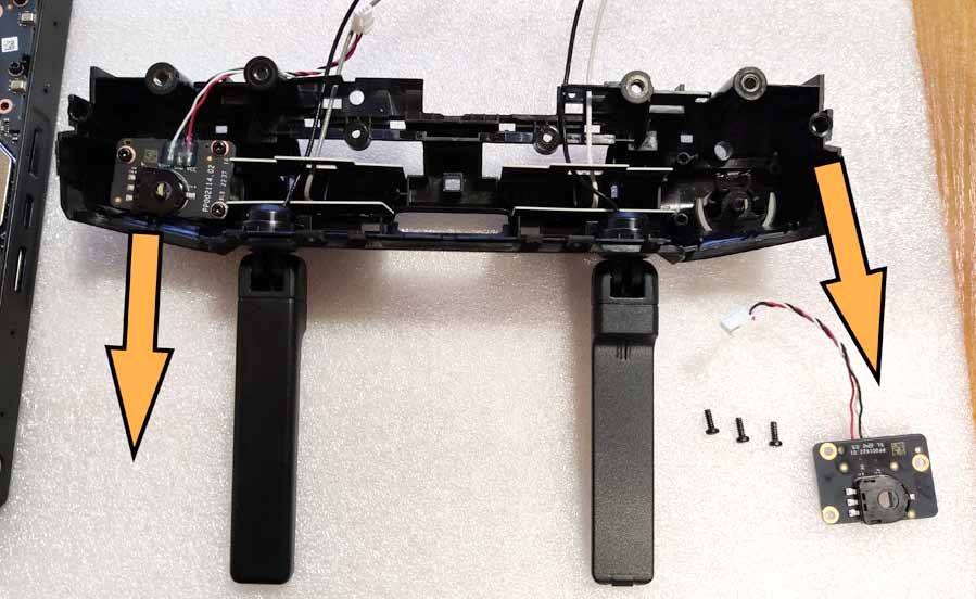
Step 29:
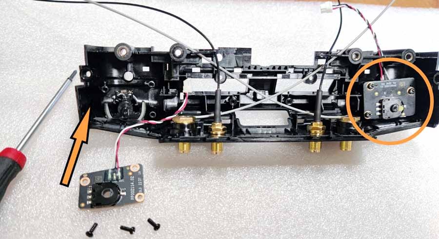
Remove the internal antennas and their shields. To remove them, you first need to remove the circuit board underneath the control wheels on the top left and top right panels. Place the removed circuit boards in a safe place.
Step 30:
Carefully feed the black cables through the holes in the screen and remove the internal antennas (with white and gray cables).
Step 31:
Pull the inner screens out (be careful - they are glued with double-sided tape!)
IMPORTANT - PLEASE PAY ATTENTION! This is the last step in the installation process before permanently modifying your controller. After this, you will not be able to undo the process and install the original antennas again.
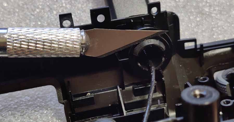
Step 32:
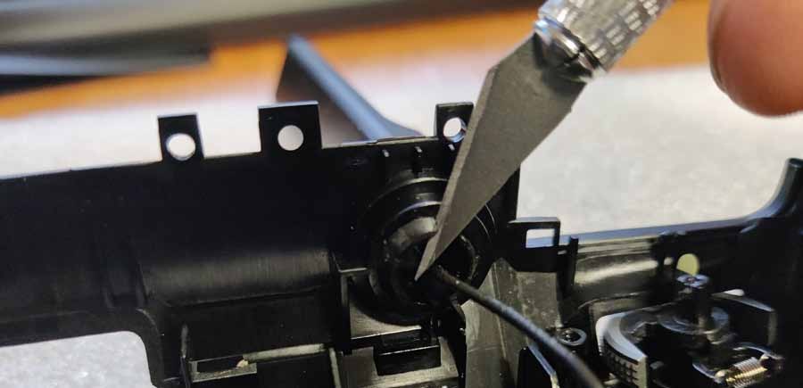
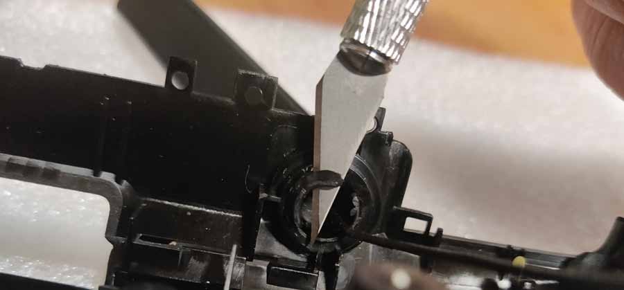
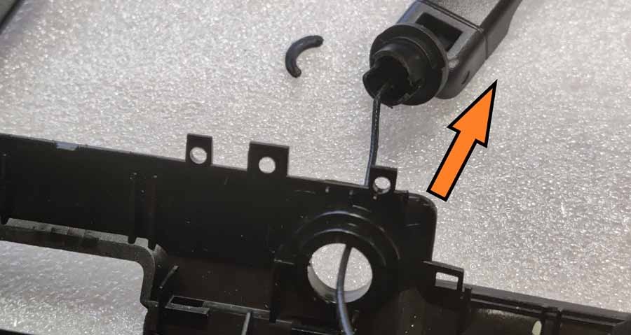
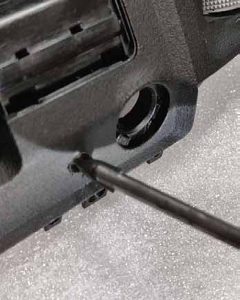
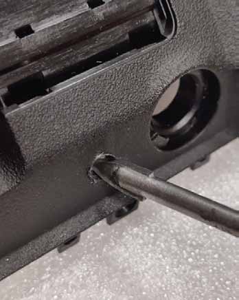
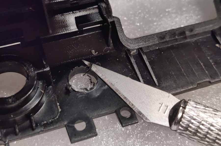
Remove the stock OD antennas. There are 2 hatches on the inside of the antenna holes that must be removed (and automatically damaged) mechanically. The best way is to cut them out with a sharp knife or insert them using a thick flathead screwdriver. Be careful not to damage the antenna wire!
Step 33:
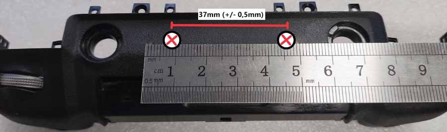
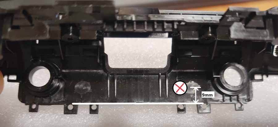
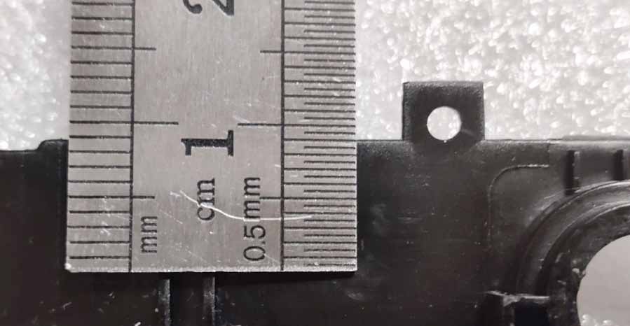
With the antennas removed, mark two points on the flat surface of the top panel where 6mm holes will be drilled. The distance between the centers of the two points should be 37mm (+/- 0.5mm) - also make sure they are perfectly centered (and the distance to the existing holes is the same on both sides). Viewed from the inside, it is best to set the center of the hole at a distance of approx. 9 mm down from the edge.
Step 34:
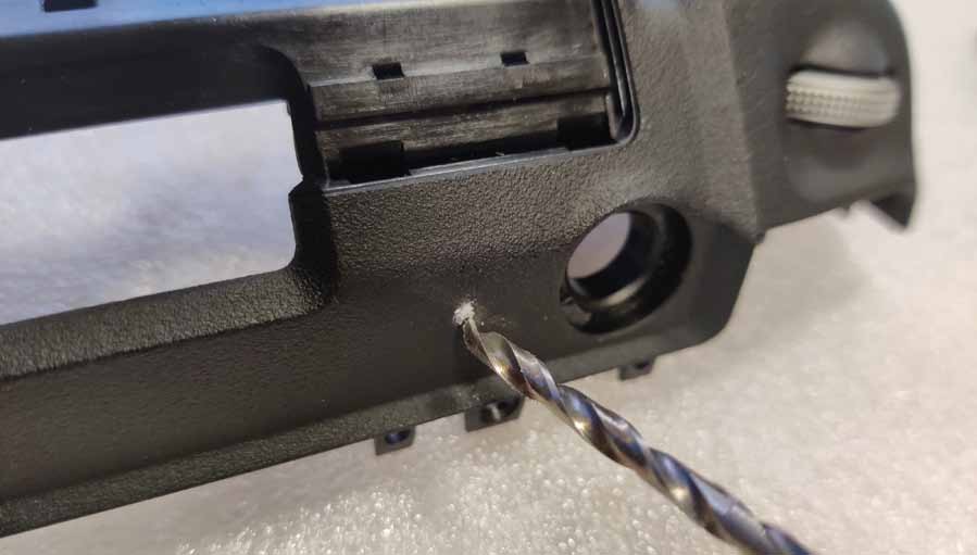
First make the installation holes with a smaller diameter drill bit (3mm recommended). Drill holes at low speed.
Step 35:
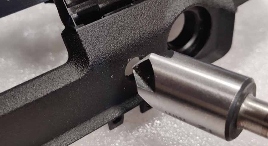
Using a larger diameter drill bit, drill out the hole (but do not use drills larger than 6mm in diameter!). We recommend using a cone drill or a ceramic drill bit.
Step 36:
To achieve a smooth, tapered hole profile, use a tapered wood countersink bit.
Step 37:
The final diameter of the drilled hole should be 6 mm (max. 6.1 mm). Remove debris from inside and, if necessary, soften sharp edges with a round file.
Step 38:
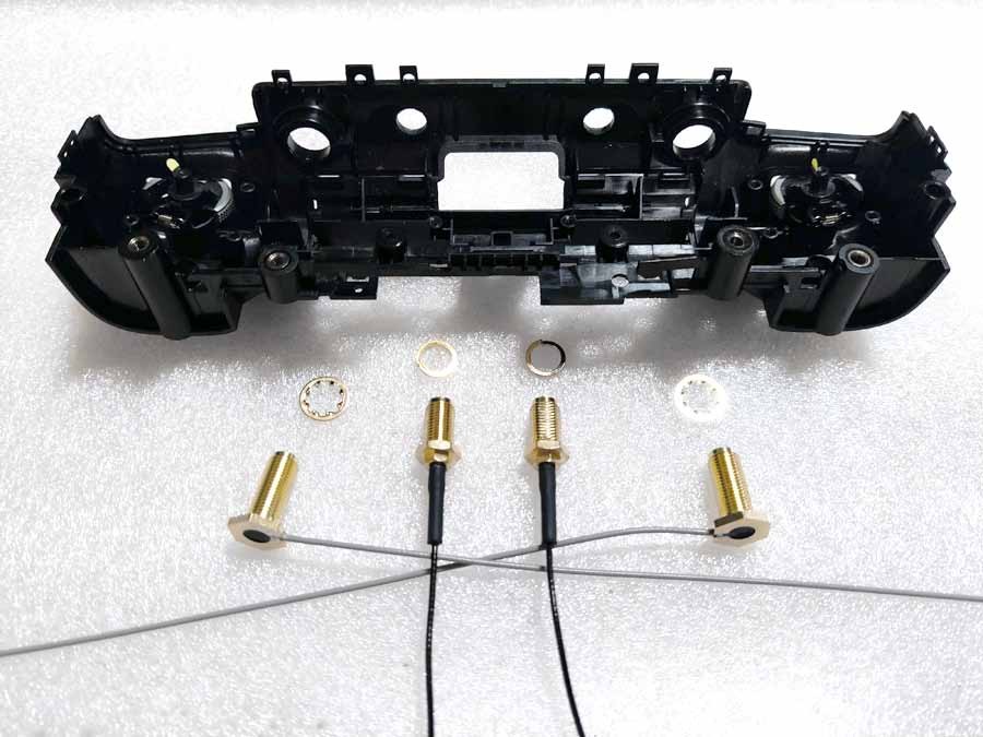
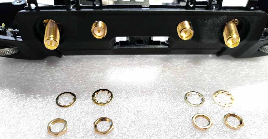
Install the 4 pigtails supplied with the antenna. Use gray ones on the outside (place a serrated washer on the threads before pushing it through the holes). Black pigtails should be installed inside (spring washers instead).
Step 39:
On the outside, first install the serrated washers and then tighten with nuts (the same on all 4 SMA threads).
Step 40:
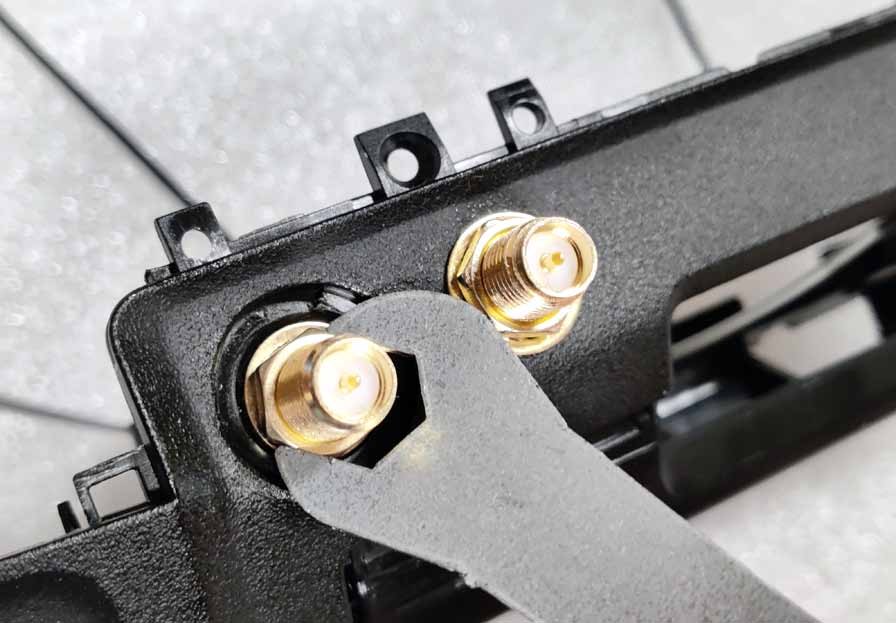
Use the included wrench to tighten all 4 nuts securely. None of the SMA ports should be twisted - it is important that they are well secured.
Step 41:
Reinstall the side wheel control board inside the top panel.
Step 42:
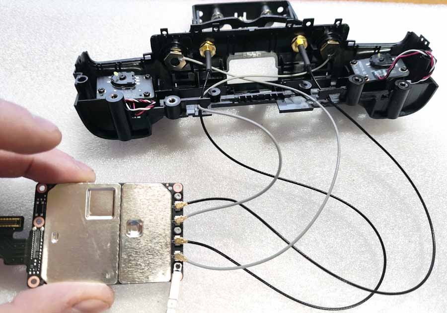
Connect the U.FL connectors to the corresponding sockets on the transmission module. There are 4 ports: ANT0, ANT1, ANT2 and ANT3. Use the diagram below to connect the pigtails to their ports and secure the connection using a metal bracket (3 screws).
Step 43:
Place the transfer module with the attached pigtails onto the PCB (but DO NOT use screws yet!). Don't forget to also "snap" the connector tape with the metal protective plate into the socket (carefully).

Step 44:
Position and secure the fan module with 10 screws.
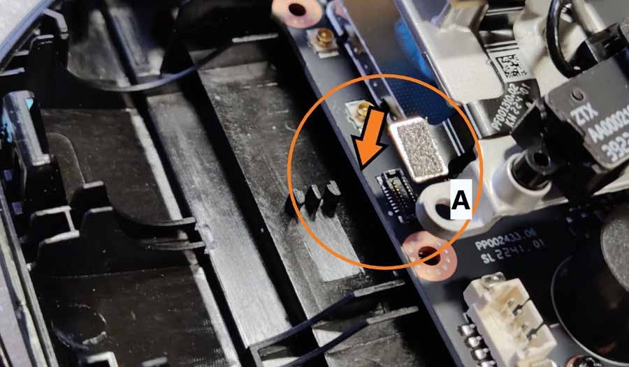
Step 45:
Don't forget to connect the tape to the PCB ("A")
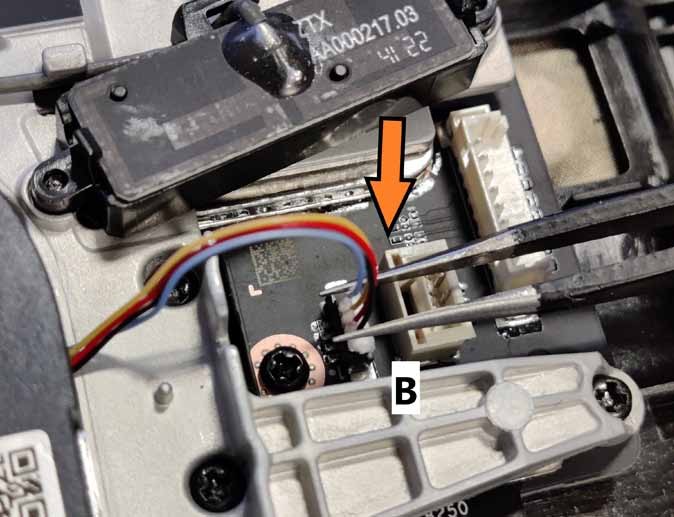
Step 46:
4-wire cable to outlet ("B")
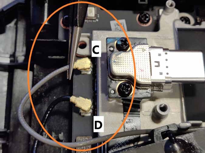
Step 47:
two U.FL connectors to the printed circuit board (“C” and “D”).
Step 48:
The last 2 screws that secure the fan module automatically secure the metal bracket above the U.FL connectors.
Step 49:
Position and secure the fan cover with 2 screws.
Step 50:
Position and secure the intercooler fan duct with 2 screws (middle of the top panel). Be careful not to damage the antenna cables.
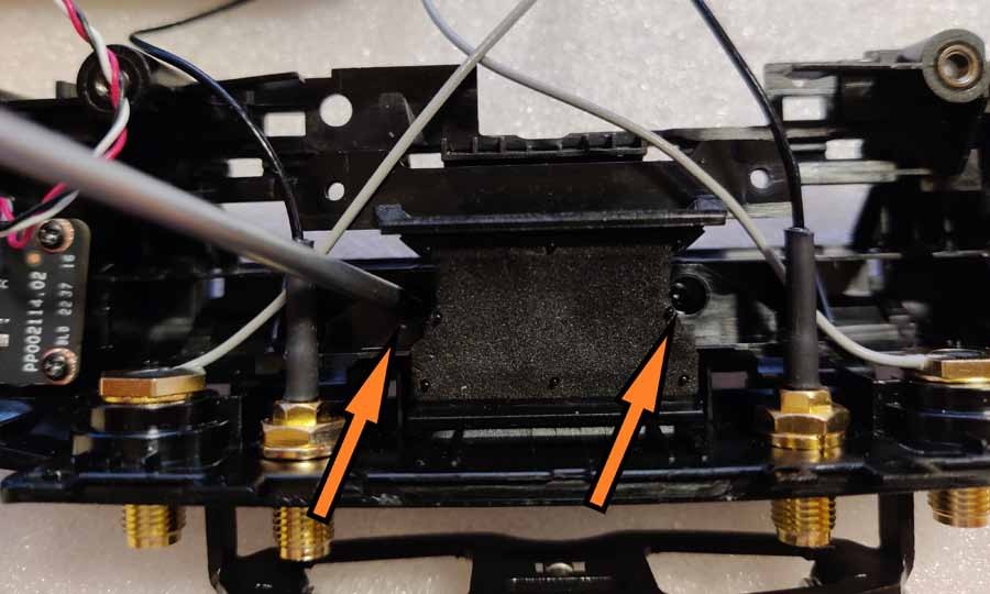
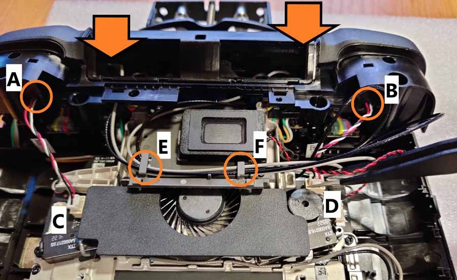
Step 51:
Pre-install the top panel into place, but do not “snap” it into place yet. Pass the white/red/black cables from the side wheels through their hooks ("A" and "B") and insert the plugs into the corresponding sockets ("C" and "D"). Pass the gray and black antenna cables through their hooks (“E” and “F”).
Step 52:
Pay attention to the correct routing of cables, replace the top panel and click it into place. All hatches should “click” and lock the panel in place. There should be no play in any part of it, and the seals on the sides and around the camera buttons should remain straight and thin. Secure the panel with two screws on the left and right sides.
Step 53:
Install the 2 screws on the top of the controller and install the LED indicator strip. Make sure the LED panel "clicks" correctly and the seal lines are straight.

Step 54:
Now install the battery cells. Be sure to connect the power connector to the white port located under the left cell and thread the battery cord through the hooks. Organize all cables inside the controller housing. Make sure none of them are blocking the screw holes and that there is no excessive tension.

Step 55:
Install the 2 screws holding the top panel in place and place the small cover holding the control knobs in place. It should "click" several times.
Step 56:
Install the back cover. Lift the right battery cell and connect the wire to its port, then put the battery back in place. Now carefully install the back cover and press it gently to connect all the hooks around. The housing should “click” several times. Start with buttons C1 and C2, and then continue to “click” down the left and right sides of the case, ending at the bottom near the USB and HDMI ports.
Step 57:
Replace the 2 screws located around the back of the compartment.
Step 58:
Install the compartment cover and secure it with 2 screws.

Step 59:
Replace the 2 screws located in the bottom holes.

Now let's install the antenna!
Step 60 :
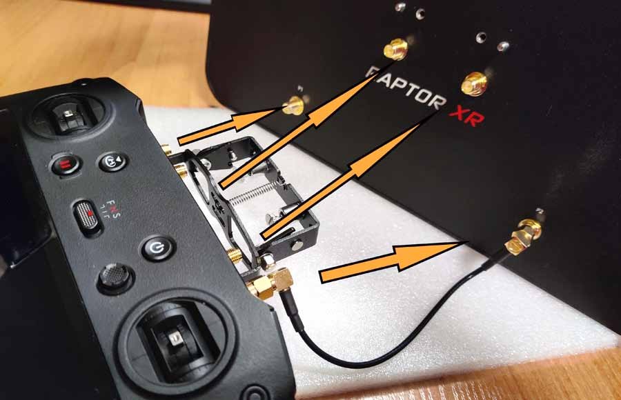
There are 4 SMA connectors through the top panel. Let's call these the "2 internal ports" (the ones that go through the drilled holes) and the "2 external ports" (the ones that were installed where the original OD antennas were once installed). Use the included mounting bracket and place it on the 2 outer ports, then secure it with nuts (use the included wrench if necessary).
CAREFULLY ! Please note, DO NOT twist the SMA port together with the nut! Don't overtighten the nut - just make sure the mounting bracket is securely seated and there is no play.


Step 61:
Using the included 15cm RP-SMA -> RP-SMA cables, connect the two external ports on the controller to the two external ports on the antenna (labeled P1 and P2). Then connect the two internal ports to the two internal ports on the antenna.
Step 62:
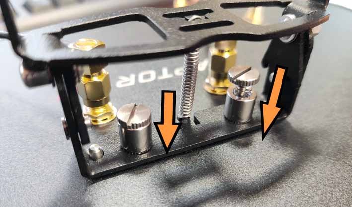
Secure the antenna to the bracket using two spring screws and make sure it is securely fastened.
Your controller is ready to work with your new 4Hawks XR antenna.